
 center and its peak voltage at its ends. The peak current at the center is very handy since it’s the antenna’s lowest impendence and the perfect location to feed the antenna from our typical 50 Ohm transmission lines. We refer to half-wave antennas as Dipoles, and they are ground plane independent.
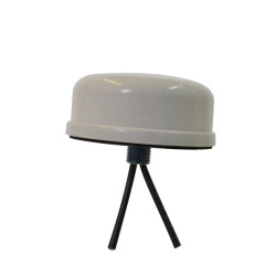 with MIMO?
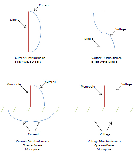
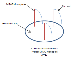
Back to our 3×3 mobile WIFI antenna example. At 2.4 GHz to get a correlation Coefficient of 0.5 we need to have our antenna elements spaced a minimum of 0.3 wavelengths apart. The resulting distance from element to element will be approximately 1.45 inches. When you add to that the quarter-wavelength ground plane requirement of 1.2 inches for each element, you can see that the 1.2 in radius from the single monopole now becomes, 1.45+1.2+1.2=3.85 inch diameter. A ground requirement like this is pretty easy to achieve, and the required antenna enclosure for the three elements can be reasonable size.
Now on to a 3×3 MIMO mobile LTE antenna. At 694 MHz the spacing required to get the 0.5 correlation Coefficient is 5.1 inches plus the quarter-wavelength ground requirement give us, 5.1+4.25+4.25=13.6 inch diameter ground plane. So the ground plane requirements for the lower frequencies become more challenging.
MIMO techniques use the fact that signals from multiple transmitting antennas, each with slightly different characteristics, will arrive at the receiving antenna at slightly different times and from slightly different directions. The old enemy of systems designer, the multi-path reflection, actually helps. The transmitters are designed to split the data stream between the various antennas and transmit them at different phases so there is an inherent delay between each transmission path. The receivers are designed to use the separate data streams to digitally reconstruct the data. The results are a data transmission which has significant increases in transmitted data rates over a conventional single data path system.
In many MIMO systems the designers have chosen not only to have the separate data paths at different times but also to have the transmission antennas at different polarizations or from slightly different antenna locations. This has multiple benefits. The first is the fact that if you are trying to communicate with a portable device you really have no control over what polarization the portable device’s antennas are at. So transmitting multiple polarizations means that one of the data streams should be near the ideal polarization. Secondly transmitting multiple polarizations also has the benefit that the multi-path reflections will be quite different for each data stream so the data will arrive at the receiver at different times. The pitfall of the multiple polarization schemes are the environment. In the old two-way radio days there were many tests run to demonstrate the fact that most reflected signals tend to become vertically polarized due to the fact that most objects in the real world that are effective reflector are vertical. This actually has a benefit to mobile users that have remote antennas mount on vehicle since most mobile antennas use vertical elements. Multiple polarization MIMO techniques really excel in an indoor environment. The surfaces in an office or home are not predominantly metal and vertical so the polarization has a better chance of staying pure. Also the transmission distances are typically shortened so there is less chance for the polarizations to change. Spatial Segregation can also be employed. In Spatial Segregation the location of the separate transmitting antennas are different, they may also be aimed at slightly different angles. Since the locations are different the transmitted signals will arrive at the receiver at different times so there can be data rate improvements.
For portable devices another challenge is the size. Nobody wants a MIMO portable device that’s 13 inches in diameter. So there are many trade-offs and pitfalls. Popular configurations for MIMO antennas used in Smart phones are: composite frame antennas, MIMO cube elements and/or Thick film Planar Inverted F’s. Many hoops need to be jumped through to make these elements work. For MIMO the main challenge is getting these elements to act as separate antennas. The spacing is so close together that the elements tend to work together as one. Exotic techniques involving phasing and neutralizing are attempted to try to isolate the MIMO elements and ultimately achieve data rate increases.
MIMO technology offers great improvements in the speed of data transmission. The future will bring many more innovative antenna schemes to cope with the pitfalls. Currently access points are commonly available with up the six separate MIMO transmission streams. Portable devices are being deployed with two and three MIMO streams. As the push for speed continues, who knows where the technology will untimely go. Ultimately innovative antenna designs along with system designer knowledge of antenna basics can tip the scales for successful MIMO deployments.
Mobile Mark manufactures quality MIMO antennas. The SMD mobile MIMO antenna is just one example.